Introduce
Corrosion problem of lithium-lead circuit
Using lead-lithium eutectic alloy as tritium proliferator/carrier provides an attractive choice for fusion reactors, because lead has sufficient tritium proliferation rate and reduced lithium stock as neutron multiplier and effective heat transfer characteristics. When using this alloy (PbLi), it is necessary to evaluate its compatibility with structural materials, mainly focusing on corrosion, mass transfer and mechanical property degradation of structural materials.
The main processes that cause materials to be corroded by liquid metal are dissolution, alloying, intergranular infiltration, impurity transfer from liquid metal to liquid metal, and thermal gradient and concentration gradient of mass transfer.
Various possible corrosion phenomena depend on many variables, including:
1. Melt itself (impurity content and composition and lithium content of liquid metal alloy);
2. Microstructure of materials in contact with lithium and lead;
3. Exposure time;
4. Velocity and profile;
5. Temperature difference on the loop (temperature difference in some specific parts of the loop, such as cold trap or pump channel);
6. PbLi temperature curve.
Although these variables are extremely important for corrosion control, some of them are the result of special interests.
CiCLo-C cycle: requirements and design
For the actual design and implementation of liquid metal loop in fusion device, there are still several most important technical problems, mainly involving material compatibility, component integration and engineering tool verification. For all these reasons, the establishment of a new corrosion loop is very popular in the field of fusion materials.
The design of the experimental section provides the possibility of studying the compatibility with other materials (coatings, functional materials, irradiated materials, etc.) and testing new experimental equipment. For safety reasons, the loop is located in a collection tray made of stainless steel (3 mm wide). The main dimension of the loop frame is 1 m 3 m, and the size of the plate is 100 mm. In order to ensure the safe drainage by gravity, the whole system is inclined to the corner of the loop connected to the special container by 4 degrees. The material of the pipe is stainless steel, 316 L, with well-known properties, and the thickness of the pipe is 3mm. The total PbLi inventory in CIC lo loop is 7 l. The loop is connected by flange joint, which is sealed by stainless steel spiral winding.
All connections are made by HANGONG connection or flange joint.
1 Main components and functions
The main components of the loop are shown in Figure 1 and described in Table 1.
Table 1 The main components of the loop are shown in Figure 1.
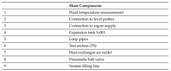
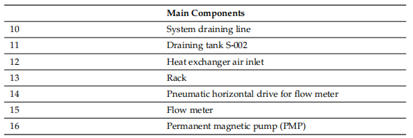
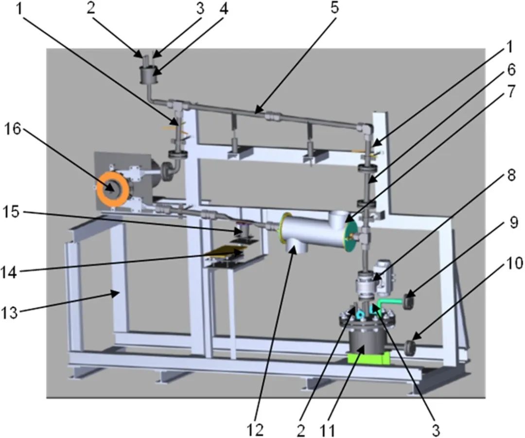
Figure 1 3D sketch of CICLO-C facility
The liquid metal loop has the main operating parameters shown in Table 2. The selection of these parameters takes into account the worst extreme conditions of the proliferation cladding.
Table 2 Main characteristics of CICLO-C

The permanent magnet pump (PMP) of SAAS GmbH is responsible for the lithium-lead circulation in the loop. Its rotor diameter is 250 mm, its power is 3 kW, and its rotating speed varies between 70 and 705 rpm. It can work at temperatures as high as 600 C. As shown in Figure 2, it can provide different flow rates at different working pressures. Therefore, PMP provides a PbLi speed range of 0.2 m/s to 2.5 m/s in TS.
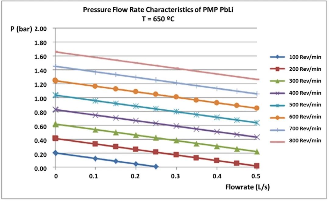
Fig. 2 Pressure-flow characteristic curve of permanent magnet pump of SaaS GmbH
At the bottom, the track system is allowed to move horizontally to compensate for the thermal expansion of the whole loop (see Figure 3). An additional expansion tank is placed at the top of the loop for filling purpose and to compensate for the change of liquid metal level (Figure 1).
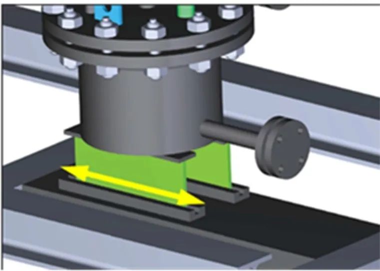
Fig. 3 details of the track system of the drainage trough, allowing movement due to thermal expansion.
The flowmeter is a magnetic flywheel flowmeter from SAAS GmbH, which consists of three main components: mechanical, inductive proximity switch and frequency and revolution relay. It is depicted by the diagram in Figure 2. 4a. The flowmeter is powered by the fluid in the pipeline above it. The rotation of the shaft is recorded by the inductive proximity switch, and then analyzed by the frequency and rotation relay. For the use and calibration of this flowmeter, it is necessary to use a special channel with a customized flat tube (see Figure 4b).

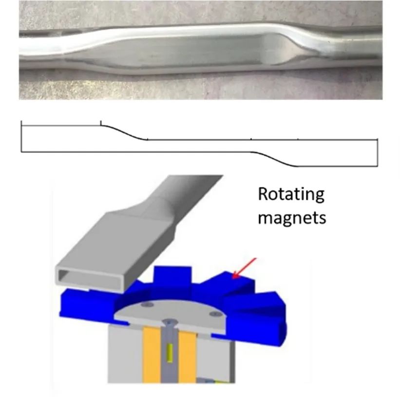
Fig. 4 schematic diagram of flowmeter (a). Custom piping (b) near the flowmeter
The temperature measurement is monitored along the whole loop by a NiCrNi thermocouple in direct contact with the outer surface of the pipeline.
Each thermocouple has a diameter of 2 mm and is inserted into the end of the sleeve (see Figure 5).
Liquid level detection is the basis of loop filling and discharging stages. The liquid level detection sensor is inserted on the covers of two water tanks (expansion tank and drainage tank). The height of liquid metal is measured by a conductive probe. Their exact length must be determined during loop debugging. The use of commercial spark plugs is shown in Figure 6.
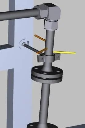
Fig. 5 fluid temperature measurement system through a three-point finger system
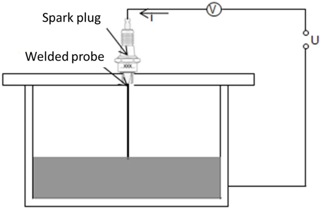
Fig. 6 Conductive liquid level detection principle
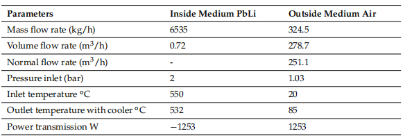
For forced cooling, the controllable heat exchanger is the moving part of the design. The transmission power of the heat exchanger is calculated for the working point of 550°C in liquid metal, as shown in Table 3. The heat exchanger can use about 1.25 kW to adjust the heat balance of the loop.
Table 3 Operating parameters of heat exchanger design
Except for the test part, the whole loop will be coated with tantalum inside. This treatment is a gas phase process, which can even coat surfaces with more complex geometries (such as fittings, elbows and pump channels). All dimensions of components are suitable for chemical coating with tantalum. As a result, the stainless steel tube obtained excellent tantalum corrosion resistance, while maintaining the mechanical properties of stainless steel, thus improving the durability of the loop itself. Samples of 316 stainless steel covered with tantalum have been produced and analyzed after several heating cycles, showing no signs of defects or deformation (Figure 7).
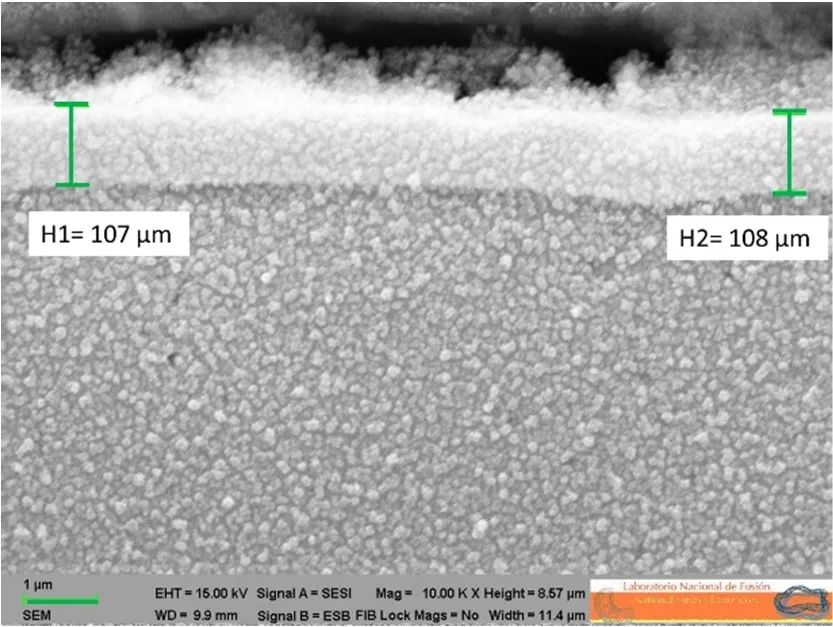
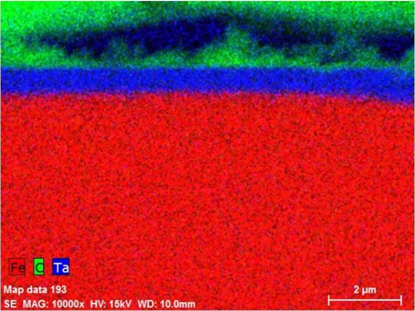
Fig. 7 SEM micrograph of a 316 stainless steel sample covered with tantalum shows good adhesion to the substrate and uniform thickness (a). EDX spectrum analysis of coated sample (b).
2 flowmeter calibration
Flywheels are used to measure liquid flow, because the rotational speed n is proportional to the flow.
The temperature of the fluid should be equal to the working temperature of the loop. The current volume flow is calculated by the following formula:

Where V is the volume flow, Pel is the electric power of the heater, ρ () is the density depending on the fluid temperature (see Figure 8), c () is the specific heat depending on the fluid temperature (see Figure 9), and 2 and 1 are the three temperature points of the fluid temperature: after PMP and before the test section.
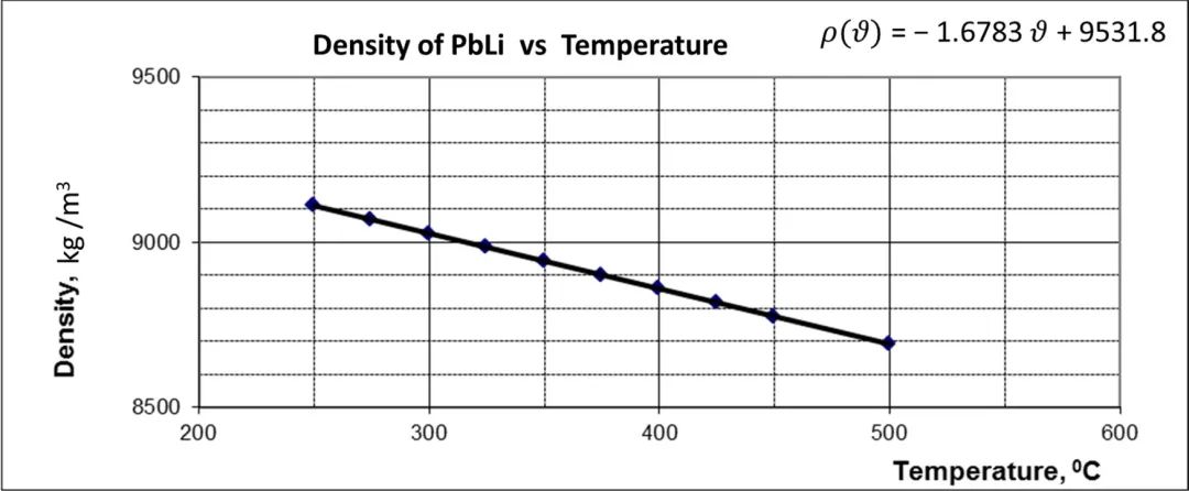
Fig. 8 changes of pbli density with temperature
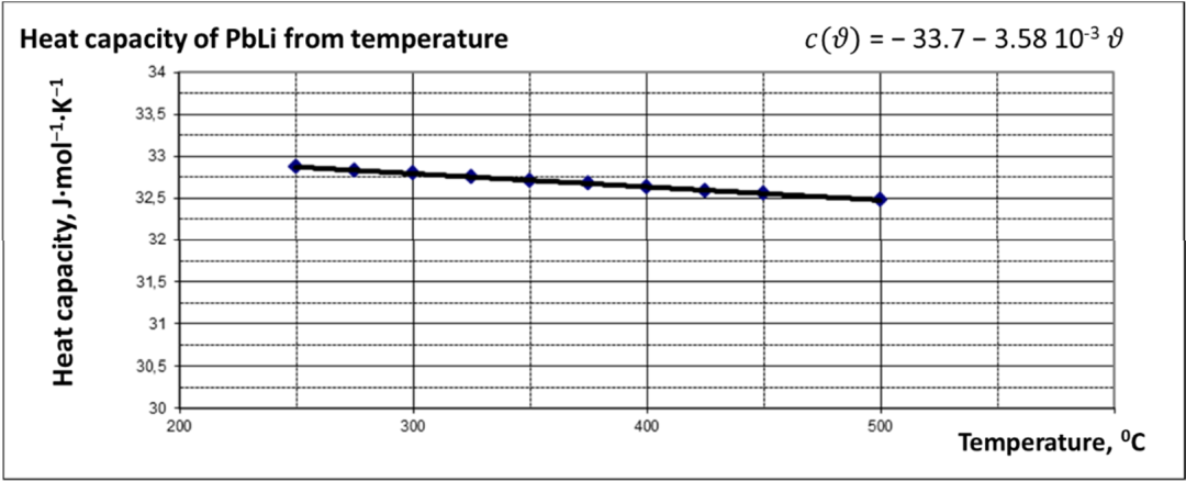
Fig. 9 dependence of pbli heat capacity on temperature
3 test area
In order to simulate the most realistic geometric environment, TS is designed as a cylindrical tube with a length of 176 mm.. All TS components follow this cylindrical configuration, as shown in Figure 10.

Fig. 10 a tubular test section with a cylindrical EUROFER sample in a 316 L pipeline.
In the main pipe, it is estimated that there are 10 annular samples and one additional sample to adapt to the flow from the main pipe of the loop to the tail side TS, 32.8±8.5±16 mm3.
The smaller diameter of TS ensures the required PbLi speed by keeping the rest of the loop at a lower speed, as shown in Table 4.
Table 4 compares the main operating parameters of TS and the rest of the loop.

The main operating parameters of TS and the rest of the loop are summarized in Table 4.
Conclusion
CiCLo-C facility will study the corrosion mechanism of nuclear materials under the most realistic conditions according to the current concept of proliferation cladding. The internal tantalum coating helps to prevent the corrosion of pipes and main components, while the cylindrical test part can reproduce the real hydraulic conditions in the rubber tube.
This facility provides a unique function for the research on the corrosion effect of nuclear materials, and provides the possibility for several upgrades in different fields (specific sensors, purification systems, magnetic field effects in corrosion, etc.). ) Conduct a more in-depth analysis of corrosion phenomenon.